Powerband RFX75 *DISCONTINUED
 Print page
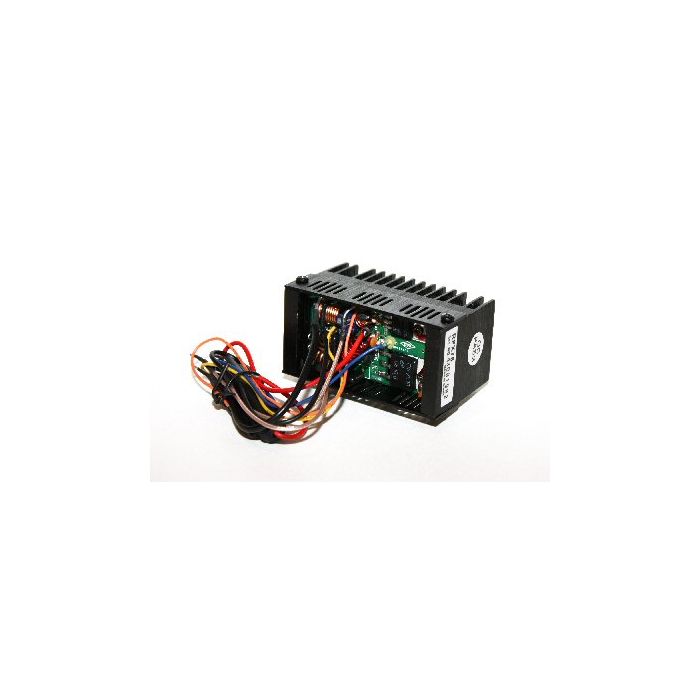
Amplifier, 75 - 100 Watt PEP Output Power, RF Final Output Stage and Low Pass Filter, Designed as a replacement and/or upgrade for most 10 meter amteur transceivers.
| Price End user EU | € 9.999,00 incl. VAT/BTW/TVA |
|---|---|
| Price End user Non EU | € 8.263,64 excl. VAT/BTW/TVA |
| Stock |
|
| Avera p/n | PWRB RFX75 |
| Brand | Powerband |
| Type | Powerband RFX75 *DISCONTINUED |
| Barcode | Not Available |
| Category | Discontinued Products |
| Sub Category | Discontinued |
| Packing Length (cm) | 10 |
| Packing Width (cm) | 9 |
| Packing Heigth (cm) | 6 |
| Packing Weight in grams | 265 |
| Packing Type | Box |
| Packing QTY in Master Carton | 10 |
| Statistical Number | 85256000 |
| Origin | China |
| Attribute Label | Not Available |
| More information | Servicedocs.com |
INTRODUCTION:
The RFX75 is a RF final output stage and low pass filter designed as a replacement and/or upgrade for most 10-meter amateur transceivers.
The RFX75 features the latest Power MOSFET technology and a built in S-meter detection circuit.
The output power of the RFX75 varies depending on the transceiver that it is installed on. Most installations will see 75 – 100 watts PEP output power.
THEORY OF OPERATION:
A basic understanding o what the RFX75 does and how it works:
a) The RFX75 replaces the transceiver’s final amplifier stage and low pass filter section.
The RFX75 is NOT a standalone amplifier. The RFX75 mounts to the back of most transceivers with little or no modification to the transceiver’s chassis.
b) Once installed, the transmitted RF signal from the output of the transceiver’s driver stage (or pre-driver stage) is sent to the RFX75 via the coaxial cable marked RF IN.
c) The driver signal is then amplified through the RFX75‘s ERF2030 (FET1) and then again through the ERF7530 (FET2).
d) The amplified signal from the ERF7530 passes through the RFX75’s efficient low pass filter.
e) A small portion of the signal is sampled through C19 and rectified through D3 and D4. This is sent to the S-meter detection circuit in the transceiver through the yellow wire.
f) The final RF output signal of the RFX75 is sent back to the radio through the RF OUT coaxial cable where it is connected with the transceiver’s antenna connector*.
g) The incoming receive signal is sampled from C14 and connected to the receive strip of the transceiver through the RFX75’s coaxial cable marked RX OUT.
* It is possible to attach the RF OUT coax directly to the antenna connector. However, it is recommended to attach it to the transceiver’s PCB because some transceivers come equipped with antenna warning systems, or other circuits, that are on ancillary boards between the recommended connection point and the antenna connector.
For many radios the installation instructions have been published on the following website:
www.cbtricks.com:80/miscellaneous/accessories/power_band/rfx_75/index.htm
LINK(S) TO VIDEO OF THIS PRODUCT:
www.youtube.com/watch?v=esDX2lVRTb0feature=related
ADDITIONAL SEARCH OPTIONS:
RFX75, RFX 75, RFX-75
This product was added to our website on Saturday 27 December 2009.
BELOW IN RED IS A LINK TO SERVICEDOCS.COM
Click the link for more detailed information on this product.